When dissimilar metals are in electrical or physical contact (the former through an electrolyte), galvanic corrosion can take place. The process is akin to a simple DC cell in which the more active metal becomes the anode and corrodes, where as the less active metal becomes the cathode and is protected. The electromotive force (EMF) series shown in Table 1 can be used to predict the metal which will corrode in contact with another metal, based on whether it is cathodic or anodic with respect to another.
Cathodic Protection is an electrochemical means of corrosion control in which the oxidation reaction in a galvanic cell is concentrated at the anode and suppresses corrosion of the cathode in the same cell. Figure 1 shows a simple cathodic protection system. The steel pipeline is cathodically protected by its connection to a sacrificial magnesium anode buried in the same soil electrolyte.
Cathodic protection was first developed by Sir Humphrey Davy in 1824 as a means of controlling corrosion on British naval ships. Virtually all modern pipelines are coated with an organic protective coating that is supplemented by cathodic protection systems sized to prevent corrosion at holidays in the protective coating. This combination of protective coating and cathodic protection is used on virtually all immersed or buried carbon steel structures, with the exception of offshore petroleum production platforms and reinforced concrete structures.
Fundamentals of Cathodic Protection
Table 1 shows the theoretical electrochemical potentials obtained by pure metals in 1 N solutions of their own ions.
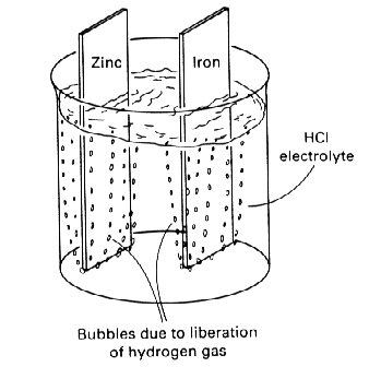
Figure 1 shows two of these metals--iron and zinc--separately immersed in a weak mineral acid. The chemical reactions that occur in
Figure 1 are:
| Fe --> Fe2+ + 2e- | Oxidation reaction |
| 2H+ + 2e---> H2 | Reduction reaction |
| 2H+ + Fe --> Fe2+ + H2 | Net reaction |
| Zn --> Zn2+ + 2e- | Oxidation reaction |
| 2H+ + 2e- --> H2 | Reduction reaction |
| 2H+ + Zn --> Zn2+ + H2 | Net reaction |
Both metals corrode, and both corrosion (oxidation) reactions are balanced by an equal reduction reaction, which in both cases involves the liberation of hydrogen gas from the acid environments. The two corrosion reactions are independent of each other and are determined by the corrosivity of hydrochloric acid on the two metals in question.
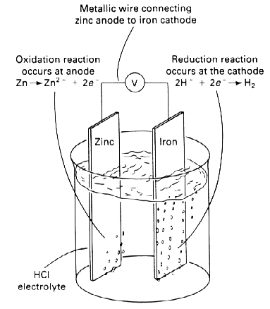
If the two metals were immersed in the same acid and electrically connected (Figure 2), the reactions for zinc would then become:
| Zn --> Zn2+ + 2e- | Oxidation |
| 2H+ + 2e- --> H2 | Reduction |
Almost all of the oxidation reaction (corrosion of zinc) has been concentrated at the zinc electrode (anode) in Figure 2, and almost all of the reduction reaction (hydrogen liberation) has been concentrated at the iron electrode (cathode). The oxidation of the zinc anode in Figure 2 is much faster than that in Figure 1. At the same time, most of the corrosion of iron in Figure 1 has stopped in Figure 2. As shown schematically, the zinc anode in Figure 1 has been used to cathodically protect the iron cathode in Figure 2.
Of course, some corrosion of the iron may still occur; whether or not this happens depends on the relative sizes of the zinc and iron electrodes. Some reduction of hydrogen may still occur on the zinc anode. The anode is the electrode at which a net oxidation reaction occurs, whereas cathodes are electrodes at which net reduction reactions occur. All cathodic protection systems require an anode, a cathode, an electric circuit between the anode and cathode, and an electrolyte. Thus, cathodic protection will not work on structures exposed to air environments. The air is a poor electrolyte, and it prevents current from flowing from the anode to the cathode.
CP can be accomplished by two widely used methods:
By coupling a given structure (say Fe) with a more active metal such as zinc or magnesium. This produces a galvanic cell in which the active metal works as an anode and provides a flux of electrons to the structure, which then becomes the cathode. The cathode is protected and the anode progressively gets destroyed, and is hence, called a sacrificial anode.
- The second method involves impressing a direct current between an inert anode and the structure to be protected. Since electrons flow to the structure, it is protected from becoming the source of electrons (anode). In impressed current systems, the anode is buried and a low voltage DC current is impressed between the anode and the cathode.
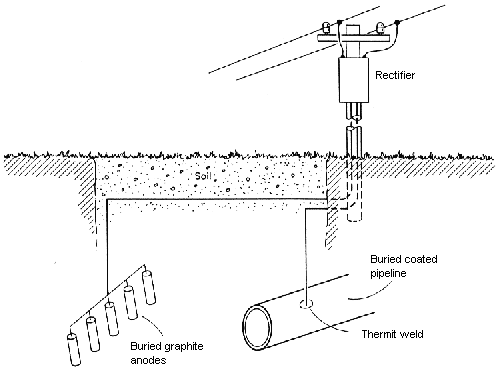
Sacrificial anode systems are simpler. They require only a material anodic to the protected steel in the environment of interest. Figure 3 shows an impressed-current system used to protect a pipeline. The buried anodes and the pipeline are both connected to an electrical rectifier, which supplies direct current to the buried electrodes (anodes and protected cathode) of the system. Unlike sacrificial anodes, impressed-current anodes need not be naturally anodic to steel, and in fact, they seldom are. Most impressed-current anodes are made from non-consumable electrode materials that are naturally cathodic to steel. If these electrodes were wired directly to a structure, they would act as cathodes and would cause accelerated corrosion of the structure they are intended to protect. The direct current source reverses the natural polarity and allows the materials to act like anodes. Instead of corrosion of the anodes, some other oxidation reaction, that is, oxygen or chlorine evolution, occurs at the anodes, and the anodes are not consumed.
Impressed-current systems are more complex than sacrificial anode systems. The capital expenses necessary to supply direct current to the system are higher than for a simple connection between an anode and a cathode. The voltage differences between anode and cathode are limited in sacrificial anode systems to approximately 1 V or even less, depending on the anode material and the specific environment. Impressed-current systems can use larger voltage differences. The larger voltages available with impressed-currents allow remote anode locations, which produce more efficient current distribution patterns along the protected cathode. These larger voltages are also useful in low-conductivity environments, such as freshwater and concrete, in which sacrificial anodes would have insufficient throwing power.
Requirements for Cathodic Protection
The original National Association of Corrosion Engineers specification for buried utility pipelines proposed the following criteria for determining when a steel or cast iron structure is cathodically protected (NACE RP0169 - NACE International):
- A voltage of -0.85 V relative to a copper/ saturated copper sulfate electrode
- A negative (cathodic) voltage shift of at least 300 mV caused by the application of cathodic protection current
- A minimum negative (cathodic) voltage shift of 100 mV determined by interrupting the current and measuring the voltage decay
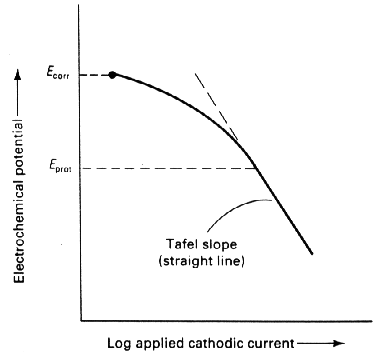
- A voltage at least as negative (cathodic) as that originally established at the Tafel segment of the E-log I curve (Figure 4)
- A net protective current from the electrolyte into the surface
All of the above criteria are currently in use, but the most common and most widely applicable criterion is the -0.85 V versus a copper/copper sulfate reference cell. Most structures can be inspected to determine if they are protected relative to this standard. The only equipment necessary is a reference cell and a wire lead that can be connected to the structure in question. The other criteria require record keeping, the ability to interrupt current (impossible for most sacrificial anode designs), and more sophisticated survey equipment. 
Figure 1: Corrosion of zinc and iron in hydrochloric acid

Figure 2: Cathodic protection of irom by zinc in hydrochloric acid

Figure 3: Impressed-current cathodic protection of a buried pipeline using graphite anodes

Figure 4: Tafel slope criterion for determining cathodic protection